Friday, December 14, 2012

Goal has been met

So... technically, I met my goal. 
Summer is long gone and we're well into December, but I have a roller!
I got my tires, tubes, and rim strips and couldn't wait to put them on. I probably should've been patient and finished the rear triangle, but I was too itchy to take this thing off the table and push it around the garage making engine revving noises...

The rear triangle is all welded, but I still need to add the smooth bronze fillets, and "cap" the tubing ends. Plus all the filing and sanding that goes with creating the smooth transitions from one tube to the next. There's probably a week's worth of hand-work waiting for me. Of course, the whole rear end needs to be taken apart AGAIN to do this... (all those engine revving sounds were totally worth it!)

This is the first time I've taken the bike off the build table. It was a pretty incredible moment for me. It's always been on that wooden table 8 inches off the ground, and it never had tires... so, even though I have drawings of exactly how tall, long, and wide the finished bike will be, it was still really cool to stand next to it in the garage and realize that the tallest part on the bike (which is the acorn nut on top of the fork cap) is still slightly under 36 inches!  As the bike sits in the pic above, I can straddle the top tube flat-footed... and I'm only 5'8". I wanted this bike to have an aggressive, low stance, and it does.

I'm totally excited to keep going, and really proud of my little creation. The 4 next things on my list of things to do will be: finish the fillets/bronzework on the rear triangle, fab up a rear stand, add the steering-stop, and make the foot peg brackets. Then the brakes will need plumbing, a seat would be nice, some way to shift the gears, something to hold gas...

But in the mean time... anyone interested in a slightly-used build table?


Saturday, November 10, 2012

Fall Progress Report

Do you remember "progress reports" in school? They would always come out half-way through the semester to all the kids who weren't doing so well... I remember they had to be signed by your parents and returned to the teacher so your folks knew that you weren't paying attention/doing your homework/etc...  That way you got it from both ends... school AND at home! I sure got my share of progress reports growing up! Why didn't those letters ever get lost in the mail?
Do schools still do that?
Anyway, I said "by the fall I'm going to have this bike rolling."
Well, it's fall... and I ain't rollin' yet...
Seems like an appropriate spot for a progress report.

I took these pics this afternoon while the sun was out. Most of the pictures I have of my bike are in a dark garage. Plus, it's usually some close-up of something...

Well, this is where I stand now. I still love it, and even though I move slow, I'm paying attention and doing all my homework...  :)

Tuesday, November 6, 2012

Been a long time since I wrote my blog...

Go ahead... sing it like the old Zeppelin song...

I think the last post was in September...
Actually, lots has happened, I just haven't spent the time in front of my computer to document it all.
Sorry Dad...
There's probably enough here for 3 separate blog posts, but because I'm so dang efficient, I'm combining them all into one tonight. Quality over quantity right?

So, I left you 2 months ago with the axle plates. Since that initial mock-up, I've added more of the "functionality" to them. The axle plates only need to do one thing: hold the axle. Brilliant, I know...
However, in order for the plates to do that, much has to be considered such as: how adjustable will the axle be? Will there be any "fine tuning?" Are they aesthetically pleasing? Do all the angles line up with the seat/chain stays? Rear disk brake, so where will the caliper be positioned? How will the caliper holder adjust with the axle? What will prevent the caliper from rotating around the axle while applying pressure to the brake rotor?

Behold, the finished axle plate:
Here you've got everything you saw in the previous post, but with the addition of the bolts for the "fine adjustment" of the axle.

This next pic shows the adjustment bolt a little better. Also, check out the drilled (for safety wire) axle nut. There is a washer on the adjustment bolt that I modified to accept the other end of the safety wire. That nut ain't goin' no where.   -Side note... Prism Motorcycle Co. absolutely NAILED the re-threading of my axle. Sorry I don't have a picture of my new threads, but as you can see, there's a nut on it so... it works.   -anyway, thanks Zach! Awesome job.

Here is the back-side of the axle plate showing the axle, brake caliper holder, and spacers:

This is the brake caliper holder guide. I can slide the axle fore and aft in the plates (to adjust the chain) and the brake caliper rides along. The 2 guides brazed to the back-side of the axle plate keep the caliper in position.

So, once it's all fitted together, we have this:
Never mind the red level on the back of the axle plate... that just shows me that my angles are right on. Also, notice the 2 seat-stays fitted (those are the 2 pieces of tubing that connect the axle plates with the main triangle of the frame) Told you I've been busy!

As long as we're talking about the seat-stays, I ordered 4 pieces of steel... one for each stay, 2 top and 2 bottom (the bottom tubes are called "chain-stays") I'll just take my time, measure twice, cut once, blah, blah, blah... Nice, gentle bend on one end, 76 degree miter on the other... length has to be perfect, notch the bottom to "bite" into the axle plate...
How hard can that be???
Well, for the first one I was too "in my head" that morning and in about 15 seconds I killed it. I had the whole thing done except for the bottom notch. I put it in my cross-slide vice, gently ran it into my cutting disk at exactly 90 degrees THE WRONG WAY! So much for my 4 pieces of steel.

But these look pretty good don't they?


...and the correct notch at the bottom... notice the bubble level, and the matching angle of the axle plate and seat stay tube... You'd think it was planned that way... I guess sometimes even I get it right.


Here are the tops all finished. Nice, smooth fillets blending from one to another. Yummy.

So my next step is to weld/finish the bottoms where the stays attach to the axle plates. I plan to "cap" the ends of the tubing somehow... I'll probably go with a "slash-cut" end, but I'm not sure yet. From there, the chain stays get bent and attached to the lower section of the frame. I'm not too worried about the brake caliper side, but the chain side will have some pretty critical bends in it. Hopefully I'll be able to take my time and not mess it up at the last step!

Then, it's tires, tubes, and rim strips...
I'll be rollin!

Thanks for your patience! I'm getting there...

Monday, September 10, 2012

Axles, spacers, brackets, more spacers...

Lots going on lately...

First of all, I'm still on track to have this thing rolling by the end of the summer. I've been working out the final design/shapes of all the rear-end parts for a while now and I'm finally done.
From my last blog entry where I posted that "drawing" of the rear axle plates, blocks, guides, etc...
I sent a digital file to Hydrocut Waterjet out in Hunnington Beach CA.
Check them out at:
www.hydrocutwaterjet.com
These guys are super professional and nice to work with. I'm definitely not "Joe-CAD-guy" and they treated me like I was. -AND they don't have a minimum order requirement! This is huge (to me anyway...)
So this little package of parts showed up on my doorstep on the Tuesday after Labor day!
What you're looking at here are the rear axle plates and axle block guides (both cut from .375 steel)
The funny looking silver things hanging of the back of each plate are the "swingarm lifters". These will be what the rear-stand hooks into to lift the rear end of the motorcycle off the ground and hold the bike steady (like a kick stand). These are .25" 6061-T6 aluminum.
Under the left plate, there's another silver thing... that's the bracket that holds the rear brake caliper. The axle passes through this bracket so when the chain gets adjusted/tightened the caliper moves with it and the wear surfaces on the rotor/pads stay consistent. -Not rocket science, as almost every bracket is this same design, but because I'm mixing/creating lots of different parts here, I had to redesign this whole layout.
For example, this caliper is from a 1990 Yamaha YZ250 dirt bike. Look and see where the caliper sits on the original bike... On the stock bike, it's about 1:00 to 2:00. On mine, it sits at High Noon.

Here's a loose fitment:
I machined the tops off the stainless bolts that are holding the swingarm lifters on... go figure. Also had to countersink the lifters so the bolts would sit flush. I love this stuff!

I put a braze joint around the outside of the axle block guide for stability (and for a nice, rounded joint between the 2 parts:
You can see the rear caliper bracket here too. This will be it's final position.
I guess looking at all these pics it may seem like there's not too much to the rear end, but I can definitely tell you that there is lots going on. I don't have any pics of the spacers, but in order to space out the axle plates evenly, there are spacers on either side of the hub that are different widths. Taking into consideration the distance between the frame tubing and the chain (don't want THAT to rub...) on the left side as well as spacing the rear caliper EXACTLY over the rotor and having enough "fore-aft" clearance so the caliper bracket doesn't touch the rear frame tubes... etc.

Easy if you're a fo-real motorcycle designer with an engineering degree and 3D CAD software... not so much if your name is Dan and you're using graphic design software to design this stuff...

Anyway, I'm not complaining. Every time I walk out to my design lab (garage) I still get excited just staring at this thing. Sometimes that's all I do... just think and stare. Some people may not get it, but from talking to my friend Jimmy up in IL, he does the same thing with the hot rods he builds. I guess I'm not the only weirdo.

The last thing I need to get done before I'm ready to attach all this stuff the the main frame is get the axle sorted.
The original Suzuki GN400 Axle is 20mm in diameter... The same as a 1990 YZ250 dirt bike. (which is where I got the rear hub/brake rotor/caliper/etc.) Lucky me. However, by utilizing a disc-brake rear wheel/hub instead of the stock GN400 drum brake, I need a little more length in the axle than the stocker. -Guess what other bike uses a 20mm axle? Yep... you guys are smart. A 1992 Honda CBR600. So, I got one.

Here is the difference between the stock Suzuki GN400 Rear Axle (on the bottom) and the '92 CBR600 Axle:
I just need to run the threads up to where I put the tape on the CBR axle. That'll be perfect.
My friend Jimmy who I mentioned earlier has family in Mooresville, NC that own a motorcycle shop called "Prism Motorcycle Co."
Check them out at:
http://prismmotorcycleco.bigcartel.com/
They'll be doing the thread-extending. Hopefully I'll get it back soon, then I can start connecting the pieces!

As always, thanks for reading!


Saturday, July 28, 2012

Just a little randomness...

This post is going to be all over the place.
I finally got the front triangle of the frame done!! It's been mocked-up, tacked, and all fitted together for what seems like years, but I finished it a couple weeks ago. There's a combination of bent, cut, rolled, mitered, and capped steel, that has all been joined by traditional oxy-acetylene welding and brazed joints. The following are some pics of the final stages:


This is me welding upside-down to uphill. My wife Deb was taking pics... it took me a little while to realize what the "flashing" was coming from...

Once that joint was welded, I covered it in bronze because I love the look of a nice, smooth fillet between tubes. This next shot is what the joint looked like after the bronze was laid down. The white/clear/glass-like stuff all around the joint is the flux. Once it cools, it literally forms into a glass-like substance. You can chip it off, but that takes too much time. I prefer to soak the joint in warm water, or for this instance where the joint is in the middle of a tube, I soaked some rags and wrapped them around the joint. Like magic, in about 20 minutes it's clean.
From there the bronze gets shaped with files and sand paper until the joint flows from one tube to the other.

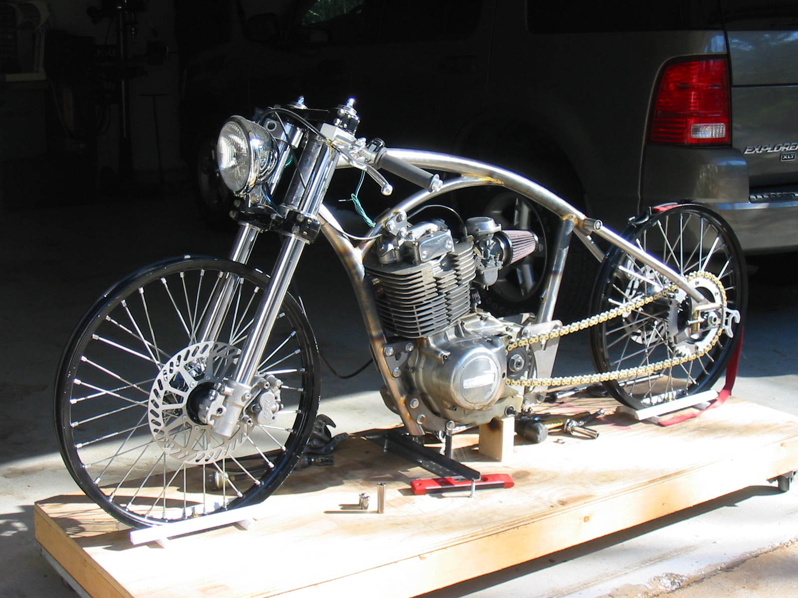
Ready for the official unveiling????

hello frame,
I intentionally cut my head off this pic due to the goofy expression I had on my face...

So this is where I change directions...
I worked so long on the front part of the frame, and somewhat neglected the final details of the rear triangle/axle plates, etc. So, it was back to the drawing board for me.
I had everything in it's place drawing-wise, I just wasn't sure about the final details such as making each piece aesthetically pleasing, finalizing up the thicknesses and type of metal for each part, and making sure my drawing will work in the real, 3-dimensional world.

This is what I'm thinking for the rear axle plates/axle blocks, fine adjusters, and bike stand lifters:
It may look a little confusing because it's the "wire-frame" view, but for my engineering friend Dave, he'll know what I'm doing here... The axle plate itself, and the axle block guides will be water-jet cut out of .375" steel. I have the axle blocks already and they're a slick cnc machined aluminum piece that has been anodized black. The "C" shaped thing hanging off the back is the lifter that the bike stand will hook into to lift the rear wheel off the ground. This will also be water-jet cut, but out of .25" aluminum. And lastly, the long horizontal screw is the axle fine adjuster... This will be brass.

I'm 99% set on this design. I've ordered my chain and will finalize the distance between the 2 axle plates once I can get an exact measurement of the chain width. I don't want my frame tubes to be too close to a moving chain!

Until the chain comes, I've put my lathe to work and designed the top "studs" that the rear frame tubes will connect to. These are the upper studs (right under where the seat will go).
As you can see, the bolt head is recessed into the stud. It has also been turned on the lathe to get the bolt markings off. You can't see it, but on the other end of the bolt, the nut (which is also recessed) has been turned on the lathe, AND the bolt length ends at exactly the outside face of the nut. (!)
This is the kind of crap you do when you have WAY more time than money! I think I have a disease...

And lastly, the stock bike had this nifty little rotary switch sticking out of the left-side engine case that would inform you of what gear you were in. There was a whole cluster of lights on the "dash" and the one that corresponded with what gear you were in would light up. I guess that kind of thing has it's place, but not on this bike. So, rather than just leaving the switch mounted to the engine and cutting the wire off, I removed the whole thing, machined an aluminum plug complete with o-ring seal on the inside, and an aluminum bar to hold it in tight. The safety wire is functional... it prevents the screws from backing out... but more than that, I think it looks cool.
Again, drilling .0625" holes in stainless cap bolts just to run twisted wire through... Yep, lots of time on my hands.
I see there's still some greasy, old dirt in the crevices of the engine cases. Camera flashes really point everything out don't they? Hopefully the soda blasting (in the future) will get the dirt and the old stained clear coat off the cases.

Thanks for watching this blog. Hopefully next time I'll have some new rear frame parts to put together!

Ciao!


Monday, May 28, 2012

More Framework

We've been on vacation this week so I've had some garage time to work more on the bike. At the beginning of our week off we had some family visit us. That was nice. Here's a pic of me and my Dad in the garage...


We were checkin' out the bike. Back when I was a little guy, my Dad and Uncle rebuilt an old Harley -which they later sold... also, I remember him rolling around on an old Honda CB175 when I was about 5. Between Dad and my Grandfather it was probably just a matter of time before I became interested in motorcycles...

Anyway, here is what I accomplished this week:

I finished the tube behind the engine (welded a cap on the bottom of the tube)


This is the finished piece. I filed and sanded everything smooth.

Next I started brazing in the "piercing tubes" into the down-tube. Here is a pic of the brazed tubes "in the raw"... which just means that I brazed them, let the tubing cool, then soaked off the flux in warm water.
The next step is to finish the joint. This is first done with a coarse round file, then a fine round file, then my sore fingers and sandpaper. I also welded the bottom cap on this tube. I didn't even need any filler rod on these caps. Just melted the edges into a solid joint. FUSION BABY!


And below is the finished tube:


And here it is installed:


Next is making sure everything is square and in position so I can attach the head tube to this down tube. Once that's done, I can weld in the backbone and engine head mount. That will complete the front triangle of the frame! Can't wait to get to that point. I'm still trying to have a roller by the end of the summer... hopefully I can keep the momentum up and meet that goal.


Thanks again for reading!


Monday, May 14, 2012

Happy Birthday to me!

Happy May 14th everyone!
-Otherwise known as my birthday.

We celebrated over the weekend and my awesome wife Deb planned out my whole day.

One of the places we went was the "Wheels Through Time Museum" in Maggie Valley NC.
We've been there before, but I love that place!
I try to explain to people that this is probably the largest collection of vintage American motorcycles in the world... and I'm lucky enough to have it right in my backyard.

So here's the ironic part: If you know me, I've never really warmed up to Harley Davidson. To me (and this is just MY OPINION... obviously I'm in the minority...) the folks on Juneau Avenue like selling the IDEA of a motorcycle/lifestyle/heritage/history/legend more than they like selling actual "engineered" motorcycles. For a company to have been in business as long as they have, they should be the kings of the world in regards to technology, advancement, engineering, performance, etc. They are undoubtedly the best motorcycling marketers on the planet! But for me, I need more than just "The legend of Harley Davidson" and a shiny, thick catalog full of bandanas, belt buckles, jackets, t-shirts, coffee cups... etc.

All that to say, back in the day (early 1900's) Harley was DEFINITELY a major player in the performance motorcycle biz... and within this tiny little window of Harley's history, I am a BIG fan.

Ok. Enough of my soapbox.
Check out some of my favorite bikes/parts from this past Saturday... and get to Wheels Through Time if you can!
This is one of the first bikes you see when you enter the museum. It's a Reading Standard Board Track Racer. This pic specifically is the seat. I LOVE this seat. It's a Mesinger Racer, and pretty much un-obtainable. There are folks making replacements so that's what I'll go with, but I think it's really cool.

This is a "Thor" board track racer. -As found. According to Dale (the museum's owner) this is the only Thor racer he's ever heard of. The cool thing about Wheels Through Time is that if you want to hear something run, just find Dale and he'll start it for you. -yes seriously. When was the last time you heard a 19-teens board track racer running? For me, it was 2 days ago. By the way... Thor motorcycles were made in Aurora, IL -about 20 minutes from where I grew up!

Not one, but 3 vintage, perfect Harley racers. (note the seats!) Also, more than just bikes, look at all the vintage stuff that surrounds these bikes! Original factory boxes containing engine parts, oil, chains, leathers, etc. How does someone find all this stuff and keep it in one place???

Hey Uncle Bob, last time I was up in IL you were asking if the museum had any Harley 8 valve engines? Yup.

But one of the coolest bikes there is a 1930 board tracker. This bike is kind of an anomaly in that by 1930 board track racing was pretty much done with. However, Harley made 20 of these engines in 1930. Note the 4 exhaust pipes... It's not an 8 valve engine though... It's a 4 valve, but each exhaust port split into two so it would breathe a little better. Believe it or not, this engine is capable of 130 mph! It's a 750cc engine. The motor was in one state and the chassis was in another, but they got them back together and fired it up. The History channel spent 350K filming a show that featured this bike being rebuilt. It hasn't aired yet, but we watched it at the museum. Super high quality, and a "must see" for anyone who is into this old stuff.

All in all, a great time. I took lots more photos, and got TONS of ideas for my bike.

It was a great birthday indeed.


Sunday, May 13, 2012

I'm Baaaaaaaack

Hey everyone,
Sorry for being such a slug and letting all this time go by without a post. You probably thought I've given up...

Well, I haven't. In fact, I've been a little busy.

I picked up where I left off with the frame and fabbed up the cylinder head mount.


This little piece of 1 inch tubing was rolled, cross-drilled, "piercing tubes" fit, and mitered. There is more work in that one piece of tubing than all the others combined! Hand-filing the miters to be as precise as I could get them... cross-boring the piercing tube holes at exactly 90 degrees... matching the radius to my already water-jet cut mounting plates... I probably went about this piece COMPLETELY in the wrong order, but hey! Alls I gots is time. I was able to go slow and make sure it fit. It does, and for this pic, it's just being held by the mounting plates. I'll weld it in soon.

Here's more of a "full frame" pic
See? It's starting to actually resemble a motorcycle!
I also worked on the "seat post." It's going to continue the arc of the cylinder head mount tube and basically "hang" off the backbone of the frame...

Like this:
That was a fun mitering job too! LOTS of filing and skin taken off my knuckles. It's such a shallow angle so it had to be done by hand. In this pic the seat tube is being supported by a wooden block on the rear rim... when it's all welded, it'll be half the length it is now, but still just "hang" off the back. I may use a small gusset underneath, but I chose a thicker-walled piece of tubing here. That should give me more surface area for making a nice, strong weld. This piece is also 1 inch in diameter and the seat will mount to this tube using a "sliding" bracket so I can position the seat fore or aft along the tube. As my drawing sits now, the ergonomics are almost identical to a 2007 Honda CBR600RR. (as far as the relationship between the footpegs, seat, and handlebars go...) I wanted to build in a little adjustability for a final fit once everything is generally in it's place.

BUT...
Probably my favorite part of the frame so far is this little "port" where I'm going to internally run the wiring. I'll have 5 wires coming out of the engine's left (magneto) side and from there, they'll enter the frame and be hidden. I cut an oval-shaped hole in the tube behind the engine and brazed in a small, curved piece of 1/2 inch thin-wall tubing. Once it was brazed, I shaped it to this nice, flowing fillet.

Other than that, I've played around with the rear axle mount plates, rear caliper mount and location, etc. I have lots more engineering to do with the whole rear end, but you can see in this pic where I'm going with the whole thing. I'm not crazy about the shape of the axle plates, but they're doing their job for now. You can see the large, cross-drilled "piercing tube" at the rear of the main frame backbone... this is where the "seat stays" will connect from the axle plated to the backbone... and from the lower section of the axle plates, tubes will connect to the lower rear engine mount... I'm sure you get the idea.
Anyway, it's really rough right now, but this is how I figure things out.


Again, sorry for all the time that has passed without an update. It's been good to get back into the garage. My goal for this summer is to have a roller! I think I can do it.


Thanks fer watchin'!

Sunday, February 19, 2012

Where have I been?

January, February, and March are the months my wife and I have designated as "home improvement months". We did this because the weather is usually cold during these months, and we can't go outside and play... so I've been making all kinds of wood chunks and saw dust instead of metal chips and sparks!

However...

I've still been able to sneak off to the garage from time to time!
I had my headlight sitting in a box on top of my work bench, and I figured I'd make a mount for it. That shouldn't take too much time should it? I wanted to make something with a "curve" in it to mimic the curvature of the frame so I got some .5" tube and started rolling it.
What I ended up with is a combination of flat bar and tubing, welded and brazed.


You can see my sickness of machining the bolt-tops on the mounts... No need for an intervention, it's just my little thing... Eventually all the bolt heads will get touched. Must be consistent!


And there's the curve.

So that's all I've really done since my last blog update...

I did go and take some pics of the bike with the headlight on, and it DOES look more like an actual motorcycle now. I also simulated the chain with some masking tape... The whole 3rd dimension thing is extremely hard for me to simulate on a computer since I don't have any CAD software, so adding real elements as I go is my only way to figure out where my "next steps" are.

Anyway, I don't see any new problems, so as soon as I get my house projects done I'll get back into it. The rear triangle, axle plates, chain adjusters, etc... are next.

Here are a couple pics of where we are now.
Thanks for your patience!