Wednesday, June 26, 2013

When we last left our hero...

He was in the process of fabricating the foot peg brackets. Let's check in on him and see how he's doing...

   Hi everyone! Sorry it's taken a while...
I finished the brackets, and have everything mounted up (minus the actual levers... more on that later)
Shift side

Brake side
I wanted to keep the "flowing curves" theme in the brackets to tie in with the rest of the bike. To me, it's a simple design, with just enough uniqueness. The levers will rotate around the peg mounts themselves right here...
They will be brazed to that rotating ring. (why was that so hard to explain last month?) I'm waiting for the levers to come from my waterjet cutter as I type this. I posted a pic of the design in my last post... I don't know if you saw it in the first of these 3 photos, but one of the 2 shift linkage rods was made and mounted to the shift arm. It's a combination of brass threaded rod, carbon fiber and stainless steel. Here's a close up:
I wanted to incorporate carbon on this bike somewhere and I thought this would be the perfect place. It's really subtle, but I think it's perfect for the application. There will be 2 rods total, the one you see pictured (which will pivot around the lower foot peg mount) and another going from that lower mount to the lever itself. I LOVE mechanical movement, and having 2 rods moving with each shift makes me all excited. (Weird huh?) I know it's not as efficient as a single rod, but it's my bike and I can do what I want!  :)

Last month, our friends Jodie and Dave came down from Chicago to visit. Dave is the guy I've mentioned before... he's a fo-real engineer and probably one of my biggest cheerleaders. He was excited to see the bike "in person" for the first time and the one thing he said that he didn't expect was how SMALL the bike was. That kind of surprised me so I wanted to see if I could capture the actual size better... I just measured the top-most part of the bike -which is the top of the fork tubes- and they measure 36.5 inches high. Or to say it another way, I'm just a tick under 5,9" and that's where my belt buckle is. Here's the bike leaning against my car. That should give you some perspective. I love that it's so small. Something about being low and long is just cool.  


So I think that's about it for this post... I took a couple glamour shots while I was at it. Remember Glamour Shots at the mall? What girl in the 80's didn't do glamour shots? I should get all dressed up in a fancy, sparkly jacket, tease my hair up with a can or two of Aqua-net, stand sideways to the camera as I pull on my jacket lapels and smile a really big Hollywood smile! Maybe next time... think I'll get any more followers?


Glamorous baby, YEAH!
Ciao...


Sunday, May 12, 2013

Foot pegs and bracketry

Bracketry. That's a cool word. I have to somehow find a way to use that word more in my everyday life...

Anyway, in today's lesson we will discuss foot pegs and their related support system. If you were to ever do a study on foot pegs (or rear-sets as they're called on racing/sport bikes) you would see dozens of different designs. Walk into your local motorcycle dealership and take a look sometime. The sport bikes have their designs, the cruiser guys have theirs, and the motocross/offroad folks have theirs. They all do the same thing... which is provide a place for your feet, but they all seem to do it in different ways.

Now take that same study, and apply it to bikes throughout history. How many ways could there possibly be to design perches to put your feet? You'll see everything from bicycle pedals on cranks (which also function as a means to start the bike...) to long, wide platforms that would fit your whole size 10 boot!

I guess unfortunately for me, the old board track racers that I'm using as inspiration for my project all had the crank and pedal arrangement. So that leaves me with my own imagination on how to design my perfect arrangement.

If you've been following this build, you will recall that I am trying to combine the antique style of an old board track bike with a modern sport/race machine. My problem at times, is that there are tons of modern, cool, race-type parts available. Although I like many of these parts... they would stick out like a sore thumb on my bike.

For example:
These pics are just a couple I found, but if you want to put aftermarket rearsets on your sport/race bike, here are some for you to choose from. The ability to adjust every possible nuance seems to be paramount...

I think I like that everything is CNC machined, eccentric-adjustable, anodized, etc...
From a geeky perspective, these parts are not only like BLING for your bike, they're also sexy to look at.

However...

These parts would look so out of place on my bike. There are "simpler" designs that cater to the Cafe Racer guys, but those too look like you just slapped on some parts that don't really fit the bike.

So, again it's back to the drawing board for me.
here's what I came up with:
Shift side
Brake side
These may be hard to see, but there is lots going on here. I thought a tubular bracket would look good with the shift and brake levers rotating around the base of the foot peg.

Starting with the "shift side", I love mechanical movement. Seeing the parts move is exciting for me. So, I wanted to incorporate some linkage as a means to shift the bike. In fact, before the "cable" was invented (throttle cable, brake cable, etc) motorcycles used solid rods connected by u-joints and clevises to adjust the throttle opening, engine timing, etc! It's pretty amazing to see how those old bikes worked. So, that was my inspiration behind the linkage rods.

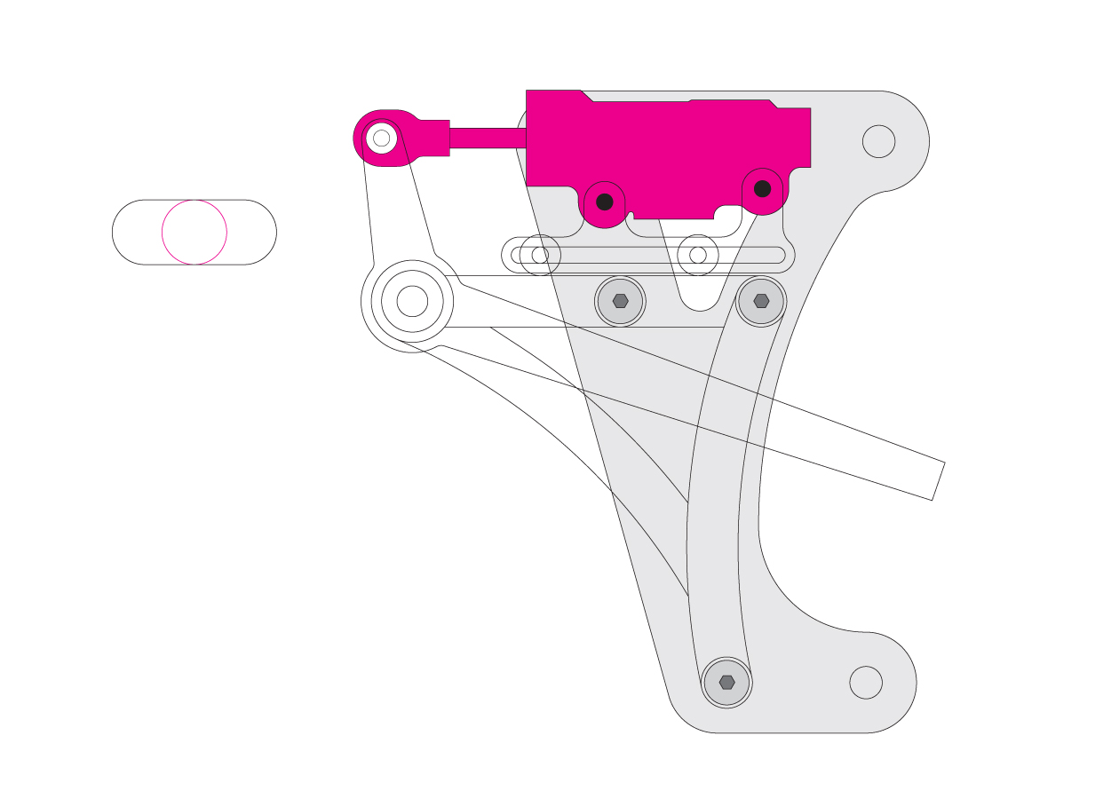
On the brake side, not many motorcycles utilize the rear brake master cylinder horizontally above the foot peg, so I figured that I'd go that route. It's a direct connection to the brake lever, and since I'm going to use SOLID stainless brake lines (like on a car) I needed a means to "adjust" the line length when I move the rear wheel back to tighten the chain... so the sliding master cylinder mount was designed. The rear wheel, brake line and master cylinder can all be moved as a unit. None of the "Z-bend" in the brake line type of adjusting on this bike!

I haven't finished the brackets or foot pegs yet, but here are some "in progress" shots machining the various fittings, bearing surfaces, etc. The drawings are what the final pieces will look like, but here they are in the state they are currently. (don't give me a hard time about all the metal chips in my lathe cabinet!)

These last pictures are of the foot peg mount and shift/brake lever bearing surfaces. It's a really simple design, but me trying to type what I did will be REALLY difficult for me. How 'bout we just wait and I'll show you the finished product? If it's a little confusing now, it'll be clear in the next installment!

Thanks for looking!
Until next time...


Wednesday, April 3, 2013

It's about time!

Hi everyone...
Glad to be back!
We've just spent the first 3 months of the year renovating our upstairs bathroom and even though I tried to work on the bike AND work on the bathroom at the same time, it didn't work. At least I tried.

Anyway, last time I wrote I had just gotten my stand done. I wanted to put my "logo" on it somehow and thought I'd try something I'd never done before... I was reading about a guy who made his own "etched brass tags". In this particular instance, he was making a head badge for his custom bicycle, but you could use the technique for just about anything.

First, you need some brass... which, by the way... the cheapest I could find for a 1 square foot piece by .0625" thick brass plate was $50!!! Brass is spendy!

Once you source the brass, you need something that will eat it. I chose these:


Whatcha have here is your basic drug-store hydrogen peroxide, and some muriatic acid. This is the Home Depot, swimming pool stuff. Mix these together 2:1 (always add the acid to the watah... like ya oughta! -remember chemistry class?) Anyway, this gives you a cheap etchant. I could've gone to Radio Shack and bought a bottle of Ferric Chloride, but it's about $17 and this was half that... you know me...

Next, you need a design for your brass "tag". I just used my last name for my "logo" and went for a simple, slightly-retro look. How do you get the design transferred to the brass? Funny you should ask... DIY electronics geeks use something called "press-n-peel blue". It's a blue "paper" that you run through your laser printer. Print your design onto the paper (reverse if you're using letters) and the toner from the printer sticks to the blue dye on the paper... which is actually plastic. Then you take your printed blue/black paper and place it face-down onto your brass. Using an iron, you re-heat the toner which transfers it from the blue paper onto your brass. Voila! Like so:


Next: BATH TIME!
I mixed up 2 parts H202 and 1 part muriatic in a plastic tub. At first, it's clear, but as the metal starts to dissolve, it turns green. By the time this brass was etched, it was a very dark emerald green.

On a printed circuit board this bath would last about 1 to 15 minutes typically. Adding heat speeds things up a little, but for my 1/16th thick brass I left it in for about 11 hours! I really wanted a deep etch, but after 11 hours my resist (the black design part) started to deteriorate also and I didn't want a pocked-up design... so I pulled it.
I would've been totally stoked if the etchant ate away half the thickness of the brass, but it didn't. You can still see the "raised" letters though, and I was very happy with the results:

NOW the work begins... cutting them out, filing the edges flush with the border. Lots of hand-work...
Here's one mounted on the stand:


Since I didn't know how this whole thing was going to turn out, I decided that I would use my left-over brass for "cut" letters also. Just in case the etching didn't go very deep, or if I ruined it, I'd just have my waterjet guy cut the letters out and I'd attach them to the brass plate. The letters would definitely stick out more, and the whole tag would be twice as "dimensional". So, off goes the brass and a pdf file was sent. This is what I got back:


I TOTALLY LOVE waterjet cutting. These letters are about 3/4 of an inch tall, and they're perfect. I was able to surface-sand each one, polish them up, and then "attach" them to my etched plates with some CA adhesive (super-glue).
I thought spray-painting the plates flat black, then wet-sanding off the high spots would look cool... so I did that, then added the individual letters... and this is the final piece:


I'm super happy with it! I had fun, and learned about chemistry.

So now you're asking yourselves... "Hey Dan, what does the summer hold?"
...Again, thanks for asking!

Goals for Summer 2013:
1.  Finish stand.
2.  Rearsets. (Foot-pegs, brackets, levers, and all linkage)
3.  Front and rear brakes (re-build calipers and master cylinders, new lines, pads, etc.)

With these 3 goals met, I'll be able to have a pretty awesome "coaster"! -I still won't have a seat, but I long for the day when I can push my bike to the top of a near-by hill, stand on the pegs and coast down to my house! I promise I won't make any goofy engine noises or pretend I'm crouching down behind my race-bike windscreen to get that last bit of aero-dynamic slipstream... but, I really want to feel how the bike rolls, turns, leans... how slow or quick is the steering... how heavy or light does it feel... what will be my "view from the cockpit... all that stuff. It's pretty weird. This thing never existed before, and now it's getting to the point of me actually being able to try it out soon. I'm nervously humble - if that's even an emotion. I'm hoping my math was right, my intuition was right, my time, imagination, fabrication, etc... and if it was, I'll have the biggest, dorky grin as I coast down my hill... again!

Thanks for reading!


Saturday, January 12, 2013

Under-STAND?

So I have this really cool motorcycle in my garage now... but it looks kinda lame with those orange jack-stands holding it up.

I need a rear-stand.

Usually people who want to race motorcycles go through a period of "race-prepping" their bikes -which involves lots of things, but one of which is taking off the side kickstand and replacing it with a rear-stand of some sort. There are lots of different styles and designs, and you can get them everywhere from Harbor Freight to HRC (Honda Racing Corp. in Japan... which means "ridiculously expensive!")
Unfortunately my bike is unique -meaning narrow- so none of the existing rear-stands will fit...

So, it's back to speedymetals.com to order up more tubing!

 Plus I got to use my new tubing bender!

It's actually kind of a copy of an HRC stand from a RS250 race bike like the one below...

My design is similar, but one of the differences is that my stand has the "spools" integrated into the stand instead of the spools being on the swingarm. Instead, the spools on my stand hook into the "lifters" hanging off the rear of my axle plates. The white discs help center the stand in the lifters.


I haven't cleaned up the stand yet... it's still raw (and a little hot) from welding and there are some "embellishments" that I will be adding...
The stand will be painted the same light blue as the bike frame, but there are some brass pieces that I'm having waterjet cut. I'm making some brass plates that will attach to the sides of the stand. These plates will be made up of 2 parts... the first will have my "logo" etched into it, and the second part will be the "letters" of the logo attached making it very dimensional. The other brass parts will be some drilled brass washers on the outside of the plastic disc-guides... and at the bottom of the stand, the tubing ends will be slash-cut and capped with a small brass plug. That should add a little bling to the stand!

...Again, too much time, not enough cash!

Here it is all together:


Thanks for watching!
More to come...
Dan


Friday, December 14, 2012

Goal has been met

So... technically, I met my goal. 
Summer is long gone and we're well into December, but I have a roller!
I got my tires, tubes, and rim strips and couldn't wait to put them on. I probably should've been patient and finished the rear triangle, but I was too itchy to take this thing off the table and push it around the garage making engine revving noises...

The rear triangle is all welded, but I still need to add the smooth bronze fillets, and "cap" the tubing ends. Plus all the filing and sanding that goes with creating the smooth transitions from one tube to the next. There's probably a week's worth of hand-work waiting for me. Of course, the whole rear end needs to be taken apart AGAIN to do this... (all those engine revving sounds were totally worth it!)

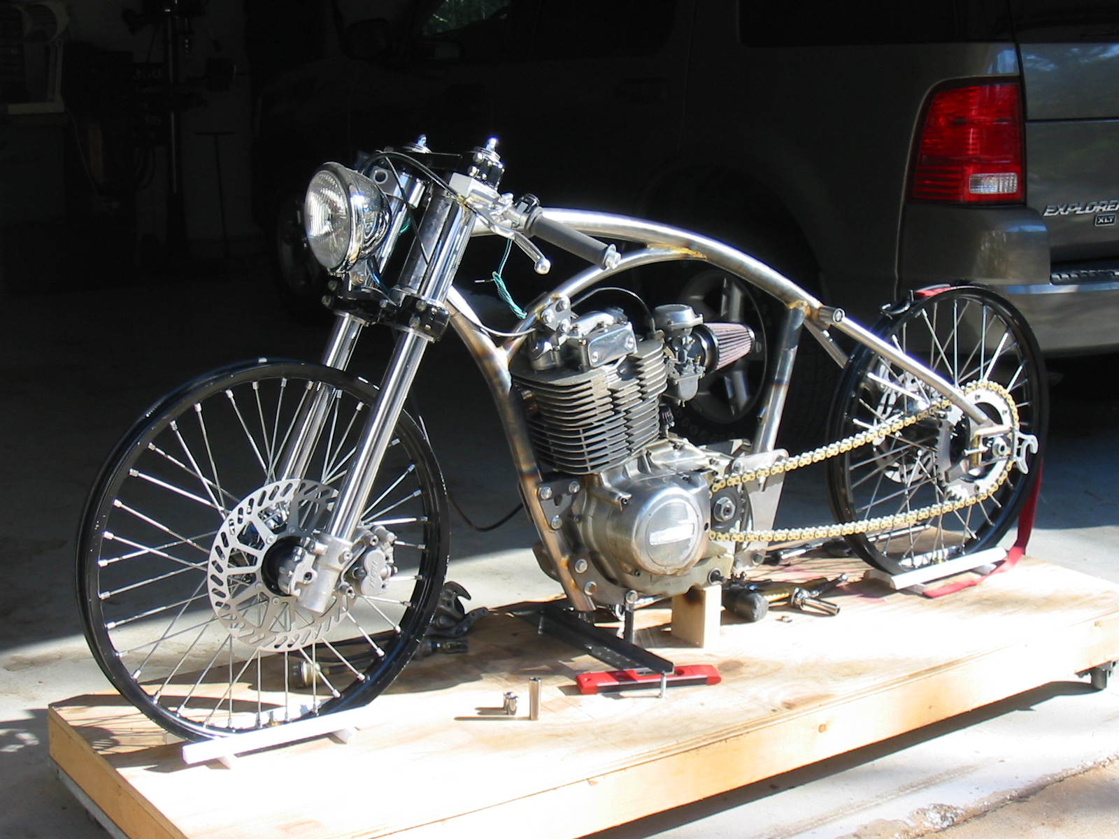
This is the first time I've taken the bike off the build table. It was a pretty incredible moment for me. It's always been on that wooden table 8 inches off the ground, and it never had tires... so, even though I have drawings of exactly how tall, long, and wide the finished bike will be, it was still really cool to stand next to it in the garage and realize that the tallest part on the bike (which is the acorn nut on top of the fork cap) is still slightly under 36 inches!  As the bike sits in the pic above, I can straddle the top tube flat-footed... and I'm only 5'8". I wanted this bike to have an aggressive, low stance, and it does.

I'm totally excited to keep going, and really proud of my little creation. The 4 next things on my list of things to do will be: finish the fillets/bronzework on the rear triangle, fab up a rear stand, add the steering-stop, and make the foot peg brackets. Then the brakes will need plumbing, a seat would be nice, some way to shift the gears, something to hold gas...

But in the mean time... anyone interested in a slightly-used build table?


Saturday, November 10, 2012

Fall Progress Report

Do you remember "progress reports" in school? They would always come out half-way through the semester to all the kids who weren't doing so well... I remember they had to be signed by your parents and returned to the teacher so your folks knew that you weren't paying attention/doing your homework/etc...  That way you got it from both ends... school AND at home! I sure got my share of progress reports growing up! Why didn't those letters ever get lost in the mail?
Do schools still do that?
Anyway, I said "by the fall I'm going to have this bike rolling."
Well, it's fall... and I ain't rollin' yet...
Seems like an appropriate spot for a progress report.

I took these pics this afternoon while the sun was out. Most of the pictures I have of my bike are in a dark garage. Plus, it's usually some close-up of something...

Well, this is where I stand now. I still love it, and even though I move slow, I'm paying attention and doing all my homework...  :)

Tuesday, November 6, 2012

Been a long time since I wrote my blog...

Go ahead... sing it like the old Zeppelin song...

I think the last post was in September...
Actually, lots has happened, I just haven't spent the time in front of my computer to document it all.
Sorry Dad...
There's probably enough here for 3 separate blog posts, but because I'm so dang efficient, I'm combining them all into one tonight. Quality over quantity right?

So, I left you 2 months ago with the axle plates. Since that initial mock-up, I've added more of the "functionality" to them. The axle plates only need to do one thing: hold the axle. Brilliant, I know...
However, in order for the plates to do that, much has to be considered such as: how adjustable will the axle be? Will there be any "fine tuning?" Are they aesthetically pleasing? Do all the angles line up with the seat/chain stays? Rear disk brake, so where will the caliper be positioned? How will the caliper holder adjust with the axle? What will prevent the caliper from rotating around the axle while applying pressure to the brake rotor?

Behold, the finished axle plate:
Here you've got everything you saw in the previous post, but with the addition of the bolts for the "fine adjustment" of the axle.

This next pic shows the adjustment bolt a little better. Also, check out the drilled (for safety wire) axle nut. There is a washer on the adjustment bolt that I modified to accept the other end of the safety wire. That nut ain't goin' no where.   -Side note... Prism Motorcycle Co. absolutely NAILED the re-threading of my axle. Sorry I don't have a picture of my new threads, but as you can see, there's a nut on it so... it works.   -anyway, thanks Zach! Awesome job.

Here is the back-side of the axle plate showing the axle, brake caliper holder, and spacers:

This is the brake caliper holder guide. I can slide the axle fore and aft in the plates (to adjust the chain) and the brake caliper rides along. The 2 guides brazed to the back-side of the axle plate keep the caliper in position.

So, once it's all fitted together, we have this:
Never mind the red level on the back of the axle plate... that just shows me that my angles are right on. Also, notice the 2 seat-stays fitted (those are the 2 pieces of tubing that connect the axle plates with the main triangle of the frame) Told you I've been busy!

As long as we're talking about the seat-stays, I ordered 4 pieces of steel... one for each stay, 2 top and 2 bottom (the bottom tubes are called "chain-stays") I'll just take my time, measure twice, cut once, blah, blah, blah... Nice, gentle bend on one end, 76 degree miter on the other... length has to be perfect, notch the bottom to "bite" into the axle plate...
How hard can that be???
Well, for the first one I was too "in my head" that morning and in about 15 seconds I killed it. I had the whole thing done except for the bottom notch. I put it in my cross-slide vice, gently ran it into my cutting disk at exactly 90 degrees THE WRONG WAY! So much for my 4 pieces of steel.

But these look pretty good don't they?


...and the correct notch at the bottom... notice the bubble level, and the matching angle of the axle plate and seat stay tube... You'd think it was planned that way... I guess sometimes even I get it right.


Here are the tops all finished. Nice, smooth fillets blending from one to another. Yummy.

So my next step is to weld/finish the bottoms where the stays attach to the axle plates. I plan to "cap" the ends of the tubing somehow... I'll probably go with a "slash-cut" end, but I'm not sure yet. From there, the chain stays get bent and attached to the lower section of the frame. I'm not too worried about the brake caliper side, but the chain side will have some pretty critical bends in it. Hopefully I'll be able to take my time and not mess it up at the last step!

Then, it's tires, tubes, and rim strips...
I'll be rollin!

Thanks for your patience! I'm getting there...

Monday, September 10, 2012

Axles, spacers, brackets, more spacers...

Lots going on lately...

First of all, I'm still on track to have this thing rolling by the end of the summer. I've been working out the final design/shapes of all the rear-end parts for a while now and I'm finally done.
From my last blog entry where I posted that "drawing" of the rear axle plates, blocks, guides, etc...
I sent a digital file to Hydrocut Waterjet out in Hunnington Beach CA.
Check them out at:
www.hydrocutwaterjet.com
These guys are super professional and nice to work with. I'm definitely not "Joe-CAD-guy" and they treated me like I was. -AND they don't have a minimum order requirement! This is huge (to me anyway...)
So this little package of parts showed up on my doorstep on the Tuesday after Labor day!
What you're looking at here are the rear axle plates and axle block guides (both cut from .375 steel)
The funny looking silver things hanging of the back of each plate are the "swingarm lifters". These will be what the rear-stand hooks into to lift the rear end of the motorcycle off the ground and hold the bike steady (like a kick stand). These are .25" 6061-T6 aluminum.
Under the left plate, there's another silver thing... that's the bracket that holds the rear brake caliper. The axle passes through this bracket so when the chain gets adjusted/tightened the caliper moves with it and the wear surfaces on the rotor/pads stay consistent. -Not rocket science, as almost every bracket is this same design, but because I'm mixing/creating lots of different parts here, I had to redesign this whole layout.
For example, this caliper is from a 1990 Yamaha YZ250 dirt bike. Look and see where the caliper sits on the original bike... On the stock bike, it's about 1:00 to 2:00. On mine, it sits at High Noon.

Here's a loose fitment:
I machined the tops off the stainless bolts that are holding the swingarm lifters on... go figure. Also had to countersink the lifters so the bolts would sit flush. I love this stuff!

I put a braze joint around the outside of the axle block guide for stability (and for a nice, rounded joint between the 2 parts:
You can see the rear caliper bracket here too. This will be it's final position.
I guess looking at all these pics it may seem like there's not too much to the rear end, but I can definitely tell you that there is lots going on. I don't have any pics of the spacers, but in order to space out the axle plates evenly, there are spacers on either side of the hub that are different widths. Taking into consideration the distance between the frame tubing and the chain (don't want THAT to rub...) on the left side as well as spacing the rear caliper EXACTLY over the rotor and having enough "fore-aft" clearance so the caliper bracket doesn't touch the rear frame tubes... etc.

Easy if you're a fo-real motorcycle designer with an engineering degree and 3D CAD software... not so much if your name is Dan and you're using graphic design software to design this stuff...

Anyway, I'm not complaining. Every time I walk out to my design lab (garage) I still get excited just staring at this thing. Sometimes that's all I do... just think and stare. Some people may not get it, but from talking to my friend Jimmy up in IL, he does the same thing with the hot rods he builds. I guess I'm not the only weirdo.

The last thing I need to get done before I'm ready to attach all this stuff the the main frame is get the axle sorted.
The original Suzuki GN400 Axle is 20mm in diameter... The same as a 1990 YZ250 dirt bike. (which is where I got the rear hub/brake rotor/caliper/etc.) Lucky me. However, by utilizing a disc-brake rear wheel/hub instead of the stock GN400 drum brake, I need a little more length in the axle than the stocker. -Guess what other bike uses a 20mm axle? Yep... you guys are smart. A 1992 Honda CBR600. So, I got one.

Here is the difference between the stock Suzuki GN400 Rear Axle (on the bottom) and the '92 CBR600 Axle:
I just need to run the threads up to where I put the tape on the CBR axle. That'll be perfect.
My friend Jimmy who I mentioned earlier has family in Mooresville, NC that own a motorcycle shop called "Prism Motorcycle Co."
Check them out at:
http://prismmotorcycleco.bigcartel.com/
They'll be doing the thread-extending. Hopefully I'll get it back soon, then I can start connecting the pieces!

As always, thanks for reading!


Saturday, July 28, 2012

Just a little randomness...

This post is going to be all over the place.
I finally got the front triangle of the frame done!! It's been mocked-up, tacked, and all fitted together for what seems like years, but I finished it a couple weeks ago. There's a combination of bent, cut, rolled, mitered, and capped steel, that has all been joined by traditional oxy-acetylene welding and brazed joints. The following are some pics of the final stages:


This is me welding upside-down to uphill. My wife Deb was taking pics... it took me a little while to realize what the "flashing" was coming from...

Once that joint was welded, I covered it in bronze because I love the look of a nice, smooth fillet between tubes. This next shot is what the joint looked like after the bronze was laid down. The white/clear/glass-like stuff all around the joint is the flux. Once it cools, it literally forms into a glass-like substance. You can chip it off, but that takes too much time. I prefer to soak the joint in warm water, or for this instance where the joint is in the middle of a tube, I soaked some rags and wrapped them around the joint. Like magic, in about 20 minutes it's clean.
From there the bronze gets shaped with files and sand paper until the joint flows from one tube to the other.

Ready for the official unveiling????

hello frame,
I intentionally cut my head off this pic due to the goofy expression I had on my face...

So this is where I change directions...
I worked so long on the front part of the frame, and somewhat neglected the final details of the rear triangle/axle plates, etc. So, it was back to the drawing board for me.
I had everything in it's place drawing-wise, I just wasn't sure about the final details such as making each piece aesthetically pleasing, finalizing up the thicknesses and type of metal for each part, and making sure my drawing will work in the real, 3-dimensional world.

This is what I'm thinking for the rear axle plates/axle blocks, fine adjusters, and bike stand lifters:
It may look a little confusing because it's the "wire-frame" view, but for my engineering friend Dave, he'll know what I'm doing here... The axle plate itself, and the axle block guides will be water-jet cut out of .375" steel. I have the axle blocks already and they're a slick cnc machined aluminum piece that has been anodized black. The "C" shaped thing hanging off the back is the lifter that the bike stand will hook into to lift the rear wheel off the ground. This will also be water-jet cut, but out of .25" aluminum. And lastly, the long horizontal screw is the axle fine adjuster... This will be brass.

I'm 99% set on this design. I've ordered my chain and will finalize the distance between the 2 axle plates once I can get an exact measurement of the chain width. I don't want my frame tubes to be too close to a moving chain!

Until the chain comes, I've put my lathe to work and designed the top "studs" that the rear frame tubes will connect to. These are the upper studs (right under where the seat will go).
As you can see, the bolt head is recessed into the stud. It has also been turned on the lathe to get the bolt markings off. You can't see it, but on the other end of the bolt, the nut (which is also recessed) has been turned on the lathe, AND the bolt length ends at exactly the outside face of the nut. (!)
This is the kind of crap you do when you have WAY more time than money! I think I have a disease...

And lastly, the stock bike had this nifty little rotary switch sticking out of the left-side engine case that would inform you of what gear you were in. There was a whole cluster of lights on the "dash" and the one that corresponded with what gear you were in would light up. I guess that kind of thing has it's place, but not on this bike. So, rather than just leaving the switch mounted to the engine and cutting the wire off, I removed the whole thing, machined an aluminum plug complete with o-ring seal on the inside, and an aluminum bar to hold it in tight. The safety wire is functional... it prevents the screws from backing out... but more than that, I think it looks cool.
Again, drilling .0625" holes in stainless cap bolts just to run twisted wire through... Yep, lots of time on my hands.
I see there's still some greasy, old dirt in the crevices of the engine cases. Camera flashes really point everything out don't they? Hopefully the soda blasting (in the future) will get the dirt and the old stained clear coat off the cases.

Thanks for watching this blog. Hopefully next time I'll have some new rear frame parts to put together!

Ciao!